ANCIENT SITES
Magnetic Readings
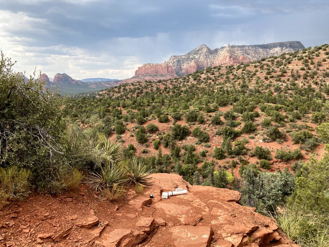
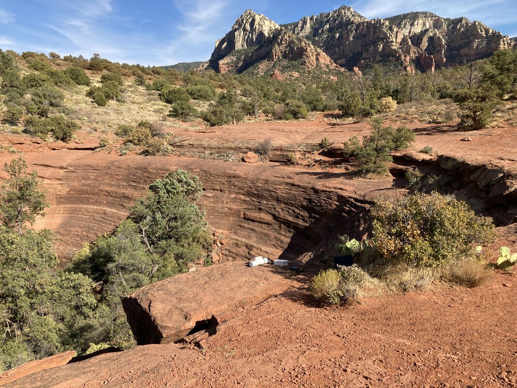
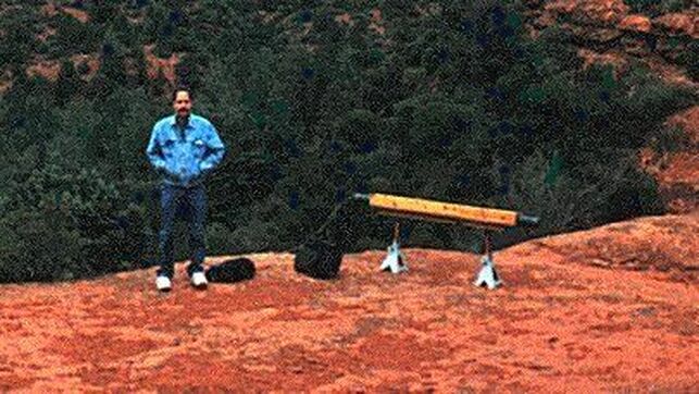
The new Geomagnetic receiving and recording system is complete and I am now recording Geomagnetic activity at different locations in Sedona, Arizona. The recorded Magnetic Data can not be heard by the Human ear so each recorded file is converted to audio frequencies so we can hear what is happening at each location Magnetically. Many ancient dwelling sites will be recorded at plus a few of Sedona's Vortex locations and caves. Although the Magnetic recordings are converted to audio frequencies they will still be an accurate depiction of what is happening Magnetically at each location. The louder sounds you hear are actually Sudden Magnetic Impulses. Bursts of Magnetic energy. In Sedona they are called a "Vortex".
Margs Draw Sedona, Arizona
Intense Outflowing Magnetic Energy.
Here the energy that is outflowing in the video above is reconnecting to the Earth's magnetic field about 200 feet away. This energy is called Inflowing. Whenever Magnetic energy leaves the Earth it must reconnect. That is the Law of Physics. So we have a spiraling Flux of Magnetic energy leaving the planet and then reconnecting to it.
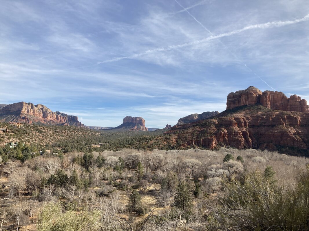
This was recorded at Cathedral Rock in Sedona, Arizona. Both Short and Long Wavelength Magnetic energy was detected as well as Inflowing and Outflowing magnetic energy.

Geomagnetic energy as recorded at The Stupa in Sedona, Arizona.

Geomagnetic activity as recorded at Rachael's Knowle in Sedona, Arizona.

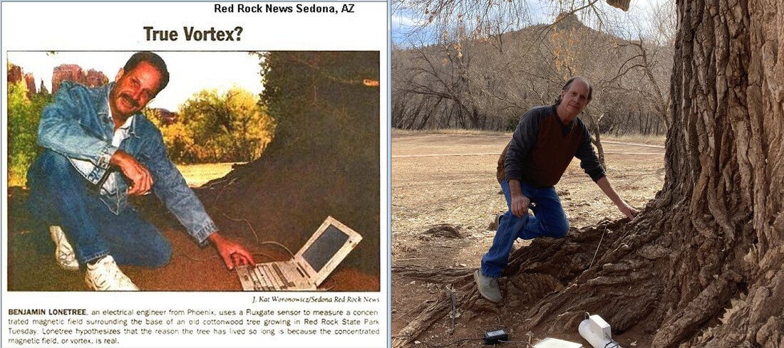
This recording has memories. It was recorded at the base of a large tree at Crescent Moon Park in Sedona. One of my first magnetic recordings were done at this tree 20 years ago. Now using more sophisticated equipment I recorded the magnetic energy at the base of this same tree again.
This magnetic recording happened at Chavez Vista in Sedona. Each location I record at has it's own unique magnetic signature. Chavez Vista is no exception.
I tried two other experiments in-between measure the magnetic energy at these locations. This time my friend Kym played a Crystal Bowl to the large ancient tree in Sedona and then she sang to the land up on Chavez Vista. An attempt to see if the tree and land would respond. In the tree video listen carefully when Kym stops playing the bowl for the trees response. You will hear a ringing as if the tree was mimicking the bowl. Chavez Vista speaks for itself. This in itself is a whole new world of exploration.
In this video I record the magnetic activity being produced by a Sedona Vortex while Kym is working with a group of four people. You will hear Kym but the dominant sounds you hear are coming from the Vortex. This was an endeavor to see if what Kym was doing created any response from the Vortex. The results were interesting to say the least. Remember a Vortex is a location where spiraling magnetic energy leaves the earth. In this case the spiraling magnetic energy flows upwards and reconnects back to the earth about 200 feet away. When people are at a Vortex location they are subject to have their brains and hence emotions influenced by the magnetic energy. You will hear the magnetic energy increase in amplitude and then subside. It does this three times while Kym is working with her clients. Please listen carefully as there are many subtle sounds happening in the audio you will hear.
Second group test with recorded Magnetic Vortex Energy.
In all the presentations on ancient Megalithic sites and places like Egypt, South America and others, I ask myself why no one has taken the time to electromagnetically measure these sites. Places like Stonehenge and other special sites were built on a grid of natural earth energy. They were done so intentionally. Certain shapes, statues, and structures were also built with electromagnetic properties built into them. I have to wonder why researchers have not taken things to the next level now that technology has provided the means to do so.
There are times I think people would rather have a big mystery rather than finding out truths. Magnetic research of these sites does not mean walking around a structure or statue with a compass or a magnetometer APP on your cell phone. You need a little more sophisticated equipment than that. I remember when I first started posting my research in Sedona. People who read my research started walking around Sedona with compasses wondering why nothing happened.
What I do took many years to develop. You can not buy equipment like I have. Walmart does not sell it or any other place. You also need to understand the data you are recording. There are times I read all the posts that I know are false to serve someone's agenda and it makes me sick to my stomach to see people falling for it. There are also times I wish I could teleport myself into the future a few 100 or 1,000 years with the hope by then people will have caught up to where I am at. That is not a slight, it is simply a comment that people appear to keep things a mystery rather than advancing their knowledge of what our ancestors knew. We have much to learn from them but we invent and speculate about what they were up to instead of learning the old knowledge. That is one of my biggest frustrations.
This is one reason I built my own very large magnetometers with miles of primary winding in the core. There is a reason why my system responds to many things other magnetometers do not. Most are fluxgate mags. that sample a collapsing field at a very slow sample rate. Fluxgate detectors, induction coils or proton precession magnetometers, measure the strength and direction of the local field.
My system is simply a very large induction coil that after the amplifier and filter stages couples into an analog to digital converter. I have the converter programmed to use a sample rate of 240 times per second! So the systems sees every little blip there is out there.

INDUCTION COIL
The induction coil. I must admit the winding of the coil on the form was very tedious and time consuming. 7.38 miles of # 28 magnet wire was consumed. " 19.6 lbs." Approximately 78,000 turns were wound on the form. The final resistance of the coil was measured to be approximately 2.9K-ohms. The wound coil was wrapped with 3M 10 mil. tape and coated with polyurethane. The laminated iron core was then inserted through the inside of the coil form with approximately 8 inches protruding from the ends. The entire assembly was inserted into the final housing which consists of 3 inch PVC drain pipe with end caps. Once the caps were glued in place two small holes were bored into the 3 inch pipe and polyurethane foam sprayed internally until the pipe was full. This adds strength to the assembly making transportation to remote locations easier without the worry of too much stress being applied to the coil and form. Electrostatic shielding was added by wrapping one turn of aluminum foil " 20 mil." around the 3 " PVC pipe. Care must be taken to insulate the ends as not to create a shorted turn. The shield was then wrapped with 20 mil. electrical tape and coated with polyurethane. The shield electrically is connected to the ground site of the Preamp/Signal conditioner input. Final weight of the coil and housing is approximately 50 lbs.
The induction coil. I must admit the winding of the coil on the form was very tedious and time consuming. 7.38 miles of # 28 magnet wire was consumed. " 19.6 lbs." Approximately 78,000 turns were wound on the form. The final resistance of the coil was measured to be approximately 2.9K-ohms. The wound coil was wrapped with 3M 10 mil. tape and coated with polyurethane. The laminated iron core was then inserted through the inside of the coil form with approximately 8 inches protruding from the ends. The entire assembly was inserted into the final housing which consists of 3 inch PVC drain pipe with end caps. Once the caps were glued in place two small holes were bored into the 3 inch pipe and polyurethane foam sprayed internally until the pipe was full. This adds strength to the assembly making transportation to remote locations easier without the worry of too much stress being applied to the coil and form. Electrostatic shielding was added by wrapping one turn of aluminum foil " 20 mil." around the 3 " PVC pipe. Care must be taken to insulate the ends as not to create a shorted turn. The shield was then wrapped with 20 mil. electrical tape and coated with polyurethane. The shield electrically is connected to the ground site of the Preamp/Signal conditioner input. Final weight of the coil and housing is approximately 50 lbs.

Electrical engineer Ben Lonetree began as a skeptic of Sedona’s metaphysical claims, so he decided to monitor Mother Nature’s heartbeat, take her pulse, and listen carefully to what She had to say. Yes, Ben is a bit of a shaman, as well as a scientist. After 10 years of research using fluxgate magnetometers and large induction coils, Lonetree can definitively state that intense electromagnetic activity abounds in Sedona. And he is ready to test other legendary sites.
Metals and minerals tend to align the earth's natural magnetism. This fact is the basis for many forms of metal/mineral detection systems. The crystalline-like structure of the metal/mineral is such that it allows the earth's magnetic field to be focused (concentrated) through the metal/mineral deposit. A proton precession magnetometer is a tool used to detect magnetic fields concentrated in this manner and is widely used for metal/mineral exploration applications.
"If people want to do what I do, the only company that makes equipment that even comes close to mine is ZONGE International. I called them once for pricing. $6,000 to $10,000 dollars."
http://zonge.com/.../geophysical-sensors-magnetometers/
"If you look at their frequency/sensitivity chart it shows their equipment only goes to 100 Pico-Teslas in sensitivity. My equipment is sensitive enough to see down to 1 Nano-Tesla. Meaning my equipment is quite a few thousand more times as sensitive as theirs."
Fluxgate Magnetometer:
http://www.watson-gyro.com/products/fluxgate_magnetometer_index.html
A fluxgate magnetometer consists of a small, magnetically susceptible, core wrapped by two coils of wire. An alternating electrical current is passed through one coil, driving the core through an alternating cycle of magnetic saturation; i.e., magnetized, unmagnetized, inversely magnetized, unmagnetized, magnetized, etc. This constantly changing field induces an electrical current in the second coil, and this output current is measured by a detector. In a magnetically neutral background, the input and output currents will match.
However, when the core is exposed to a background field, it will be more easily saturated in alignment with that field and less easily saturated in opposition to it. Hence the alternating magnetic field, and the induced output current, will be out of step with the input current. The extent to which this is the case will depend on the strength of the background magnetic field. Often, the current in the output coil is integrated, yielding an output analog voltage, proportional to the magnetic field.
Fluxgate magnetometers, paired in a gradiometer configuration, are commonly used for archaeological prospecting.
A wide variety of sensors are currently available and used to measure magnetic fields. Fluxgate magnetometers and gradiometers measure the direction and magnitude of magnetic fields. Fluxgates are affordable, rugged and compact. This, plus their typically low power consumption makes them ideal for a variety of sensing applications.
The typical fluxgate magnetometer consists of a "sense" (secondary) coil surrounding an inner "drive" (primary) coil that is wound around permeable core material. Each sensor has magnetic core elements that can be viewed as two carefully matched halves. An alternating current is applied to the drive winding, which drives the core into plus and minus saturation. The instantaneous drive current in each core half is driven in opposite polarity with respect to any external magnetic field. In the absence of any external magnetic field, the flux in one core half cancels that in the other and the total flux seen by the sense coil is zero.
If an external magnetic field is now applied, it will, at a given instance in time, aid the flux in one core half and oppose flux in the other. This causes a net flux imbalance between the halves, so that they no longer cancel one another. Current pulses are now induced in the sense winding on every drive current phase reversal (or at the 2nd, and all even harmonics). This results in a signal that is dependent on both the external field magnitude and polarity.
When you truly understand things like entropy and negentropy and understand Torus, (Rodin), Mathematics it will open the door to an understanding of yourself and the universe. To keep it simple if you can understand that you are an electromagnetic being and the energy field that surrounds your body is in a toroidal shape you will be on your way. Also remember all matter is a vibrational state of energy. The lower the vibrational frequency the more dense it becomes in the physical world. When you meditate, listen to tones of different frequencies like chanting, playing Quartz or Tibetan bowls, and a host of other things they stimulate your Torus shaped electromagnetic body.
(c) 2019, Iona Miller and Ben Lonetree; All rights reserved.
5-9-19 -- I am having a special custom Ferrite Rod made up to cover a frequency range of DC to 30Hz. This will be for a new light weight sensor to use for magnetic research at ancient sites. I improve on these Ferrite rods once I receive them. The new rod, (core) will be 1 inch in diameter and 15 inches long.
I will wrap it in shrink tubing and then apply a layer of MetGlass over the insulated core. MetGlass has a permeability of 2,000,000. Yep 2 million for those who understand permeability. MetGlass is made from a Cobalt/Nickle alloy that gives it a high permeability. This will make for a fast frequency response as magnetic flux changes through the core and MetGlass so I can detect any sudden magnetic shift in a given area where I am researching.
The core will be wrapped with approximately 10 pounds of #28 copper wire so the overall weight of the completed sensor will be less than 15 pounds. Easier to transport to sites rather than my 30 pound sensor or 60 pound sensor. The MetGlass will also act to capacitively lower the frequency response of the sensor to make it more efficient at Ultra Low Frequencies. The amplifier circuit I will build to go with it is a voltage amplifier. I do not use a differential circuit. I have found amplifying voltage and sampling it instead of differential voltage makes for a more sensitive system.
The voltage amplifier circuit will also incorporate a lowpass filter with a high end cutoff frequency of 30Hz. to reduce any harmonic noise from the power grid at 60Hz. The power grid puts out such a signal into the atmosphere even if I am 10 miles from the nearest power lines I can still detect it. I would also like to find a small laptop computer with USB ports. One that can except an operating system like Windows 7. I want to have a lightweight system I can transport in two backpacks making it easy to haul into remote sites. This will be fun when everything is complete.

2020 SYSTEM
December 31, 2019 at 10:14 PM · Finished. I have been burning the midnight oil building this. Usually stopping for the night at 4am. But it's finally done. Tomorrow or the next day I will take everything outside away from all the power grid noise in the house and let it run for an hour. The sun is quiet now but if it even whimpers a wee bit the sensor should record it.
https://www.facebook.com/benjamin.lonetree/videos/2804967869581671/
the new system today. Just need to permanently wire it now and install the circuit board into it's enclosure on the sensor tube. Then I will be ready for field tests.
https://www.facebook.com/benjamin.lonetree/videos/2804967869581671/
the new system today. Just need to permanently wire it now and install the circuit board into it's enclosure on the sensor tube. Then I will be ready for field tests.
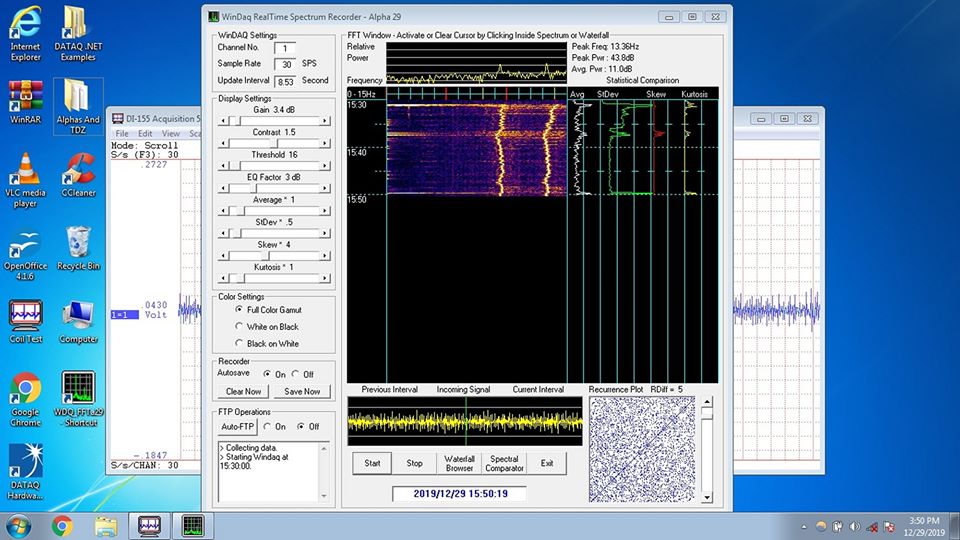
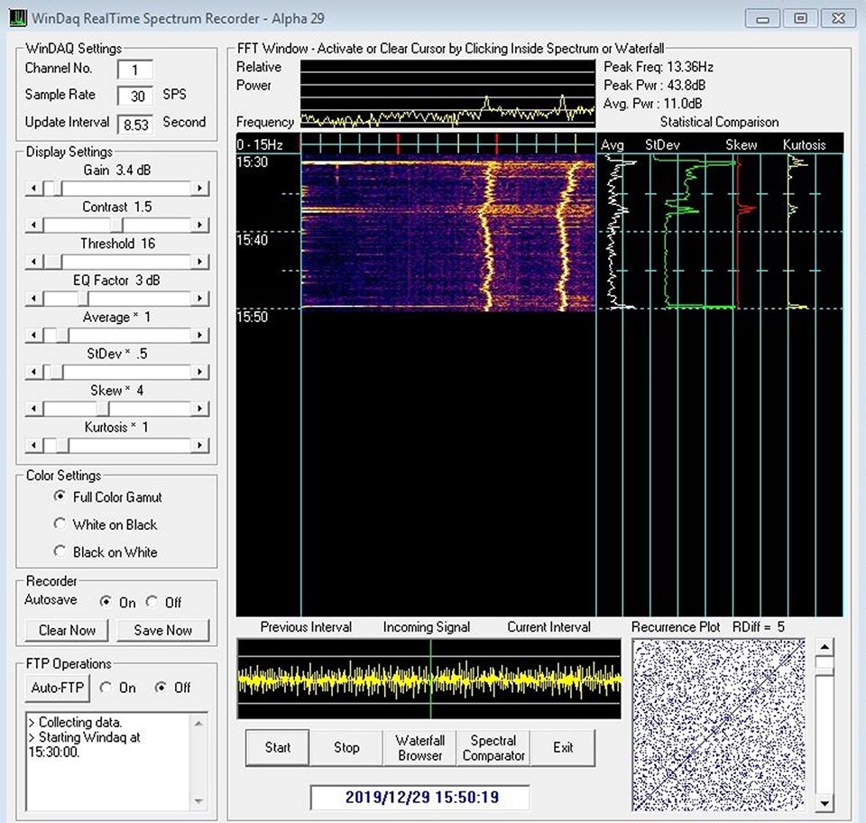
So here is the first hour long chart from the new sensor system. Lots of cultural noise. Meaning things like the electrical signature of my refrigerator, furnace, me opening and closing the fridge door, me walking around and for that matter the cat walking around. Remember the system is running inside the house in the kitchen. Once it is outside in a quiet remote location the only thing it will record is natural earth stuff, solar and space stuff, and anything else that might be producing a signal in the area the sensor is located.
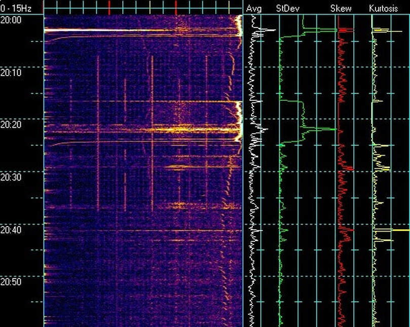
I will do my best to explain what you are seeing. Years ago I was involved creating software and systems for detecting earthquakes before they happened. My self and two other gentlemen. One was Ernst who was a PHD computer professor at a major university in Germany. The other gentleman was named Michael. Michael was a former spook for the government. Secret stuff. Both men were brilliant. Ernst died in his sleep in his 50s. Michael just plain vanished. The two created specialized software that works with the analog to digital converter I have. All three of us used the same data acquisition modules. Now this software they created was called The Alpha Series. There were 30 versions created as we developed things through the years. I have every one including the source codes used to create them. To my knowledge I am the only one who has them. They are not commercially available. I installed the Alpha 17 version on my field computer. It works perfectly with the sensing system. It records and every hour on the hour it saves the chart and data. Then it resumes recording. The chart tells me what peak frequency my sensor detects plus many other things.
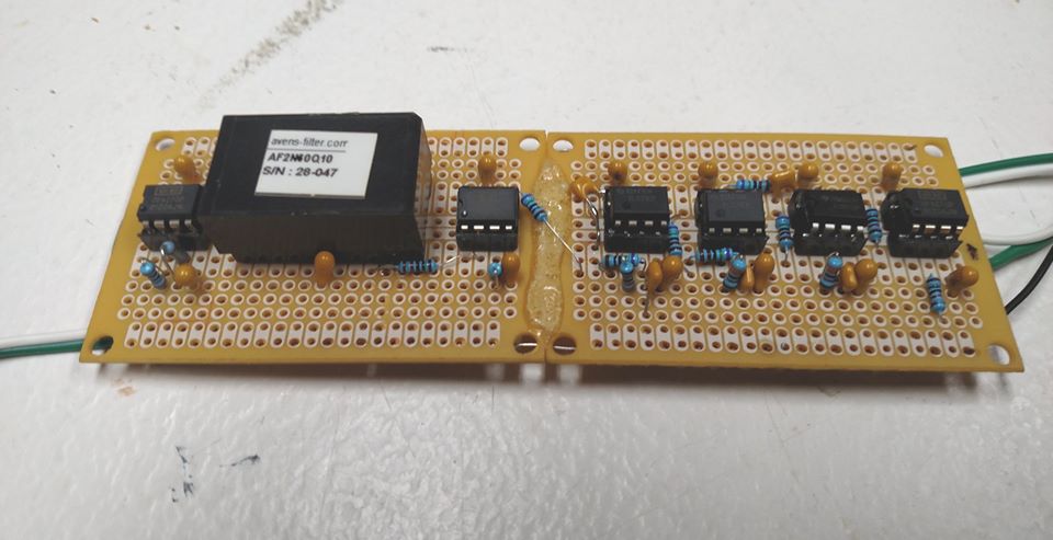
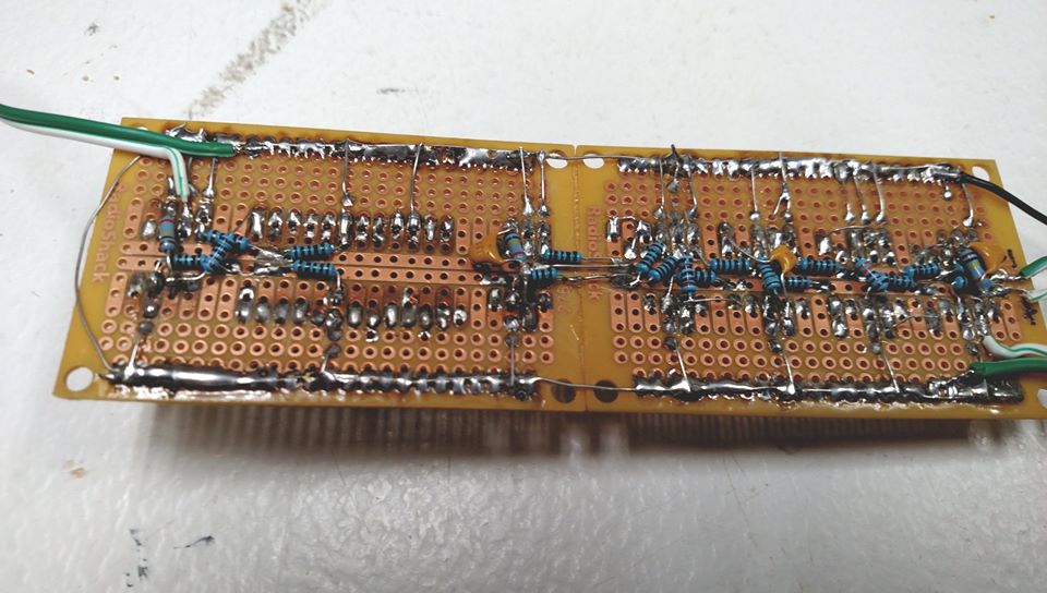
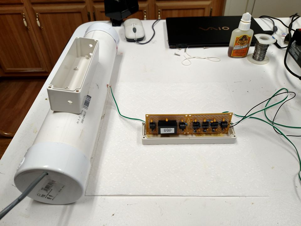
December 29, 2019 at 2:25 AM · Ok. The electronic circuit for the new electromagnetic sensor is finished. This thing turned out hotter then I expected which is wonderful. In the video you will see me point the camera at the magnet on the floor. I barely move the magnet and the chart goes off scale. I also later pass my hand near the sensor without touching it and the sensor detects the electrical energy from my body. This thing is hot, hot, hot! And I am delighted. For those who understand instead of using an active lowpass filter made up of operational amplifiers I used a passive circuit. Resistors/capacitors. It goes between the 2nd. stage amplifier and the final 3rd. stage amplifier. By using a passive circuit I eliminated three electronic circuits using op-amps. Less parts to fail. The entire receiver now only uses three OPA27 op-amps and one 60Hz. notch filter made by Avens Company. My Schumann Resonance design uses 9 operational amplifiers and one 60Hz. notch filter. Electronically I have simplified everything and made things lighter so it all fits in a back pack. Now all I need do is mount everything permanently in an enclosure and this system is ready. It will be a special summer measuring energy in Sedona. I am looking forward to it. This design is very stable and reliable. That's what is needed.
Oh now..... I am back to using my creation. It rocks. What you see in the beginning is just background stuff running in the house. I reach and pick up the magnet and wave it about 5 feet away from the sensing coil and you can see the large increase in magnetic disturbance. For those that understand I am just using a first stage amplifier, than a 60Hz. notch filter to get rid of the power grid noise, and then one more stage of amplification. Now I will add six poles worth of lowpass filtering with a cut off frequency of about 20Hz. Lowpass means only signals that happen below 20Hz. will be detected. This new sensing system will really work wonders. Not only will it detect magnetic anomalies in any area I choose to test it will also detect electrical anomalies. So far so good. My design is also nice and stable. It does not even require a zero offset bias circuit. I know I am being technical but I know of no other way to explain things. Some here will understand.
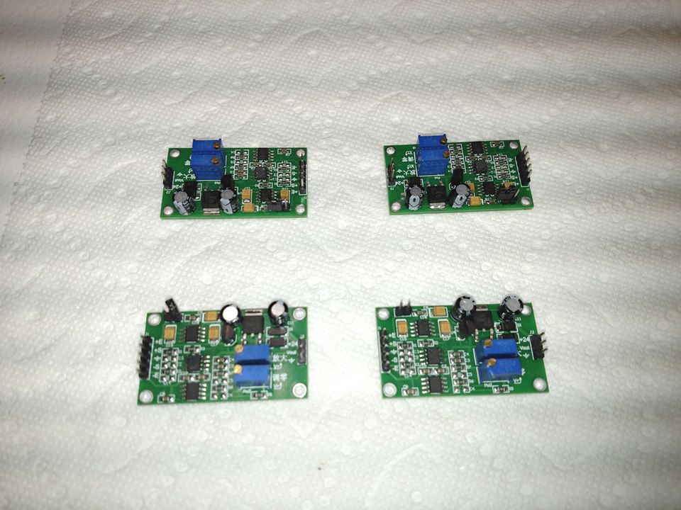
On a happy note the new magnetic sensor electronics is finished. I need to test it now. I will still be testing the other boards I ordered that are pre-assembled. They use the AD 620 chip which is a great chip. My boards are super sensitive as I designed them for Schumann Resonance recording. I am still trying to come up with something not as difficult to build as my creation so people can do this easier.
Oh now..... I am back to using my creation. It rocks. What you see in the beginning is just background stuff running in the house. I reach and pick up the magnet and wave it about 5 feet away from the sensing coil and you can see the large increase in magnetic disturbance. For those that understand I am just using a first stage amplifier, than a 60Hz. notch filter to get rid of the power grid noise, and then one more stage of amplification. Now I will add six poles worth of lowpass filtering with a cut off frequency of about 20Hz. Lowpass means only signals that happen below 20Hz. will be detected. This new sensing system will really work wonders. Not only will it detect magnetic anomalies in any area I choose to test it will also detect electrical anomalies. So far so good. My design is also nice and stable. It does not even require a zero offset bias circuit. I know I am being technical but I know of no other way to explain things. Some here will understand.
On a happy note the new magnetic sensor electronics is finished. I need to test it now. I will still be testing the other boards I ordered that are pre-assembled. They use the AD 620 chip which is a great chip. My boards are super sensitive as I designed them for Schumann Resonance recording. I am still trying to come up with something not as difficult to build as my creation so people can do this easier.